Back
Ram Air Drag Recovery Parametric Assessment
Use this tool to perform a conceptual analysis of the drag recovery potential of your ram air cooling duct as a function of the thermal energy transfered to the cooling airflow, flight conditions and ducted HX thermohydraulic performance. 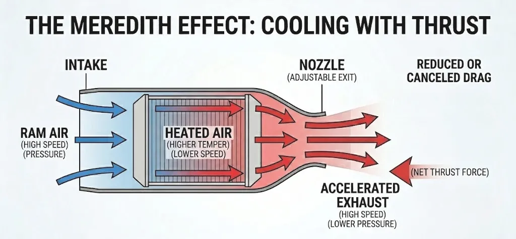
The drag recovery of the ram air cooling duct is expressed using the Thrust Ratio
TR = (Tn / Dg) - 1 ,
where Tn is the nozzle thrust and Dg is the gross drag of the duct. TR reflects the aerodynamic efficiency of a cooling duct: a TR value of zero implies a neutral impact of the ram air duct on the aircraft aerodynamics, while positive and negative values indicate net thrust or drag, respectively.- Step 1: Problem DefinitionDefine temperature offset from the international standard atm., assume an intake design MFR and estimate a duct-only total pressure ratio (often approaching unity).
- Step 2: Parametric AnalysisVary all parameters to display the thrust ratio (TR) of your duct as a function of the ram air temperature increase (x-axis).
- Step 3: GuidelinesFind optimal combinations of flight conditions and duct design parameters that, for a feasible (depending on your application) cooling flow temperature increase, minimizes drag or maximizes HX pressure drop for a given TR.
Remember!
- TR = 0No net drag
- TR < 0Duct introduces net drag!
- TR > 0Duct produces thrust!
Offset value from ISA
Assuming no HX
Design massflow rate ratio of intake
Intake datum drag coefficient
Adjust Parameters
Operating massflow rate ratio
Duct total pressure ratio 0.956
Total pressure 55584.2 Pa
Total temperature 7.7 C
FAQs
It is an aerothermodynamic principle whereby the drag introduced by an air cooled ducted heat exchanger is offset by the thrust produced by accelerating the heated ram air through a nozzle. The drag reduction - or drag recovery - potential of such ram air cooled ducts is highly dependent on the duct and heat exchanger design, flight conditions and integration of the duct within the aircraft.
It is a simple metric that expresses by how much I can reduce the drag of my cooling duct by leveraging the acceleration of the cooling air that was heated by a heat exchanger (or radiator). The most versitile metric for expressing the drag reovery potential is the Thrust Ratio as a function of the ram air temperature increase ΔT.
The TR equation (Ch.5, Eq. 25 of the PhD Dissertation by F. Beltrame - 2026) has been derived using a dimensionless balance of momentum between the incoming ram air flow and the heated cooling flow exiting the duct nozzle. A subsonic scoop intake model is used to estimate spillage and datum drag.
Every intake is designed to operate optimally at a specific mass flow rate ratio. Usually, at the optimal MFR, the lip suction effect of a scoop intake balances the small spillage drag. The net spillage drag at the design MFR is therefore zero. Typical values of design MFR for subsonic intakes range from 0.55 to 0.75.
By multiplying the thrust ratio TR times the gross drag (D_g) of the duct. But... at the preliminary design phase you might not know the D_g of your duct. No worries! You can estimate D_g using the ram drag, the datum drag coefficient (Cdd), and by assuming negligible negligible spillage drag: D_g = ( 1+ 0.5*Cdd ) × ( mdot_air × v_cruise ). For example: a duct with TR = -0.15 for ΔT = 48°C, and a cooling duct which processes 10 kg/s of air at a cruise speed of 208 m/s, introduces a net thrust of -330 N (drag). Assuming no heat rejection, the TR decreases to -0.22 an the drag increases to 482 N.
The drag recovery potential (Meredith effect) for the specified conditions can be assessed immediately by looking at the chart. On the leftmost side of the chart, there is no heating (no air temperature increase in the HX). As heat is rejected to the airflow, the total temperature increases as ΔT= Q_HX / (mdot × cp). Therefore the slope of the TR curve represents by how much the net drag can be decreased by rejecting heat to the airflow.
This is a very difficult question to answer in a few sentences! Let's walk through an initial estimate for a testcase together, this way you can replicate it for your system. First, let us assume we are dealing with the ram air coolung duct of the TMS (thermal management system) of a high temperature (HT) PEM fuel cell stack. The cooling loop working fluid (pressurized water-based mixture) enters the ram air-cooled heat rejector at 100 °C. Assuming a flight speed of M=0.55 at 5km, the inlet temperature of the HX is approximately 0°C. Assuming my FC stack has an optimistic efficiency of 50% and needs to provide 0.5 MW of electrical power, for a ram air mass flow rate of 10 kg/s the air temperature increase is 50°C, which corresponds to a HX effectiveness of approximately 0.5. In such conditions, assuming a pressure drop in the HX of 500 Pa and 3% total pressure losses in the duct, I obtain TR= -6.6%, which translates in a net drag of roughly 120 N. If the HX pressure drop doubles, the net drag increases to 172N. If I can reduce the duct-only total pressure loss by 1%, the net drag of the duct decreases again back to roughly 115N. You can now keep testing and analyzing the effect of all these parameters and how, by changing the HX effectiveness or air mass flow rate, the results change.
To neglect the intake model, adjust the slider such that the operating MFR == design MFR. In such cases, the intake only contributes to the drag with a small fixed datum drag coefficient. You can also set this coefficient to 0 to completely remove the intake drag contribution.